플레이트 및 프레임 열 9 팁 기 - 3
TIP 3: Avoid Situations Where Pressure Spikes Can Occur
Although manufacturers make extra allowances in the design engineering, it is important to stay within the pressure limits of the heat exchanger's rating. If a pressure spike within the system piping is possible due to the quick closure of a valve, water hammer, etc., you must take the necessary precautions to protect the heat exchanger or suffer the leaky consequences of a blown out elastomeric gasket. Avoid pressure changes of more than 150 psig/min and temperature changes of more than 20oF/min (11oC/min). Remedies for this situation include relief valves, rupture discs, pulsation dampers and arrestors. Check with the manufacturer for recommendations.
TIP 4: Use a Strainer or Bypass the Unit During Startup
During startup, it is advisable to include a temporary strainer on the cold or hot water inlet as well as the inlet of the process liquid. Altern- atively, bypass the heat exchanger altogether during startup. Even if your liquids are clean, with no particulates present, a temporary strainer or bypass configuration around the PHE is recommended for new, startup applications. During construction, it is all too common to see dirt, weld beads and other debris get into tanks and piping, and then get pumped through the system. (I once found a work boot in the suction line of a large pump.) If this debris finds its way into the exchanger, it may get trapped, causing an increase in pressure drop and a decrease in heat transfer efficiency.
![]()
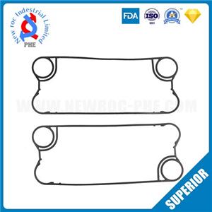
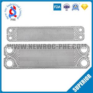
Figure 2. The plates in a plate-and-frame heat exchanger typically are in a chevron or V-shape. Every other plate is reversed, causing a waffle-type grid between those plates. Most PHEs will allow 0.0625" or smaller particles to pass through without fouling. For liquids containing larger particles, wide-gap plate designs are available.
TIP 5: Keep Large Particles Out
The plates in a PHE typically are in a chevron or V-shape (figure 2). Every other plate is reversed, causing a waffle-type grid between those plates. The space between the plates is called the channel and, in many cases, can be quite small to achieve higher levels of heat transfer efficiency.
Particles entering into the exchanger can potentially get caught in the plate channel, so it is important to ensure that no particulate larger than 0.0625" is allowed to enter the heat exchanger. If your liquids could contain larger particles, they should be removed with either a strainer or separator prior to their entering the exchanger. This is especially important if there is an open tank in the system where larger particles could be introduced. Increased velocity is not only important for efficiency, but also to help keep particles in suspension so they pass through the exchanger. Most plate-and-frame heat exchangers will allow particles 0.0625" or smaller to pass. For liquids containing larger particles than this, "wide-gap" plate designs are available.
![]()
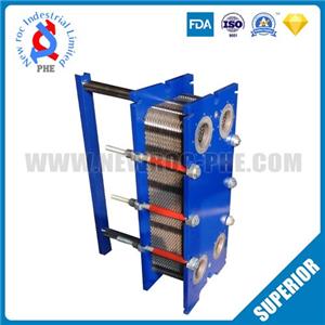
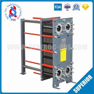
Figure 3. The total dimension of a plate pack is based on the number of plates and grids in the unit. This distance is measured between the inside of the head and follower. You should check this dimension and tighten the unit, if necessary, at least once a year.
TIP 6: Periodically Check Plate Pack Dimensions and Frame Integrity
Generally, it is easier to prevent a heat exchanger from leaking than to stop a leak once it occurs. An important point to remember is that a plate-and-frame heat exchanger is not tightened to a torque specification but rather to a platage dimension. Between each pair of plates is an elastomeric gasket that, as compressed, seals the area between the plates and prevents leakage. Picture a large heat exchanger with perhaps 600 to 700 plates, each with a gasket between them, and you can imagine how much compression will take place when you start to close the unit by tightening the tie-bars.
The manufacturer will provide a total dimension of the plate pack based upon the number of plates and grids in the unit (figure 3). This distance is measured between the inside of the head and follower. It is recommended that you check this dimension and tighten the unit if necessary, at least once a year. At the same time, check the tie-bars and frame components for any damage or corrosion that could occur in chemical environments.
TIP 7: Use Good Piping Practices
As with all process equipment, good, common-sense piping practices should be used. A heat exchanger makes a lousy pipe hanger. Ensure that all piping is supported properly and does not put any undue stress on the connections to the heat exchanger.
In steam applications, ensure that all condensate lines are properly pitched away from the heat exchanger so that condensate will not mix with the steam and flash back into vapor. One cubic foot of water evaporated at 212oF (100oC) and 14.69 psig becomes 1,606 ft3聽of dry saturated steam! Steam traps should be included and used in accordance with local codes.
TIP 8: Take Precautions to Minimize Port Erosion
A safe rule of thumb is to keep port velocity at the heat exchanger around 20 ft/sec. In addition, consider port liners of the same material as the plates, even on water applications. These liners, available in many different alloys, will protect the carbon steel head from erosion and corrosion in high flow, abrasive applications. As an example, in a sea (salt) water application, it would be common to use a carbon steel frame with titanium port liners and plates. This practice ensures that any components in contact with the seawater would be constructed of the corrosion-resistant titanium.